Figure 1: LSR
Ken-ichi Nagami (ken.nagami@toshiba.co.jp)
Toshiba
Japan
Hideaki Imaizumi (hiddy@wide.ad.jp)
Keio University
Japan
Osamu Nakamura (osamu@wide.ad.jp)
Keio University
Japan
Hiroshi Esaki (hiroshi@wide.ad.jp)
University of Tokyo
Japan
Label switching technology enables high performance, flexible, layer-3 packet forwarding based on the fixed length label information mapped to the layer-3 packet stream. A Label Switching Router (LSR) forwards layer-3 packets based on their layer-3 address information or their label information mapped to the layer-3 address information.
LSR requires one label per one packet stream. Therefore, the evaluation of the required number of labels are important from the viewpoint of the implementation and the scalability of LSR. The required number of labels depends on a label mapping trigger and a granularity of a packet stream.
Two typical label mapping policies have been evaluated with an actual traffic trace. One is traffic-driven label mapping with host-pair packet stream. This policy is used for IFMP[1] and FANP[2, 4]. The other is topology-driven label mapping with a destination network packet stream. This policy is used for TDP[3]. The evaluation shows that both mapping policies will require a large number of labels in an inter AS.
In this paper, we discuss several label mapping policies in an intra AS and inter AS. Based on the evaluations, we propose the hybrid label mapping policy to establish LSP, i.e., topology driven for intra AS and aggregated flow driven for inter AS. Regarding the inter AS, we evaluate the number of labels for the several label mapping policies using the real traffic trace. In the intra AS, we compare three label mapping policies. One of these label mapping policies is a flow aggregation using OSPF. LSP (Label Switched Path) is established between an ingress router and egress router which are border routers in an OSPF area. We evaluate this label mapping policy in the actual LAN environment.
The label switching concept enables layer-3 packets to be forwarded either using the layer-2 label (e.g., VPI/VCI) or using the shim label [7] between the layer-2 header and layer-3 header. The label is used as information to forward the packets without analyzing the layer-3 address (e.g., IP address). This means that the label represents the destination address of the layer-3 packets. By using the label instead of the layer-3 address for packet forwarding, the LSR does not need to look up anything in the best match policy based routing table, whose search key is the layer-3 address.
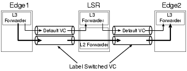
The packet forwarding at the LSR is shown figure 1. The LSR has a layer-3 forwarding engine and layer-2 forwarding engine. It is connected with two LSR-edge routers (Edge1 and Edge2).
LSRs are connected with two types of VC. One is the Default VC, and another is the Label Switched VC.
The Default VC is used for conventional packet forwarding. For example, when Edge1 sends a packet to Edge2 using conventional packet forwarding, Edge1 sends the packet through the default VC. LSR receives it and transmits it to the layer-3 forwarding engine through the layer-2 forwarding engine. The layer-3 forwarding engine of the LSR looks up the routing table according to the destination of the packet and sends it through the default VC. Then, Edge 2 receives it. LSR forwards the packets using the layer-3 engine.
The Label Switched VC is used for cut-through packet forwarding. For example, when Edge1 sends a packet to Edge2 using the cut-through packet forwarding, Edge1 sends the packet through the label switched VC. LSR receives it and forwards it using only the layer-2 forwarding engine to send it through the Label Switched VC. LSR forwards these packets faster than with the conventional forwarding because LSR doesn't need to look up the layer-3 packet. The conjunction of the Label Switched VC is called the Label Switched Path (LSP).
A relationship between the label and the packet stream needs for LSR to forward packets using the label. Label Distributed Protocol (LDP) [6] establishes the mapping between the label and the packet stream.
One of major applications of LSR is ATM-LSR, that contains the ATM switch module as a layer-2 forwarding engine. ATM-LSR has to allocate a reassemble buffer space for each label. Therefore, each ATM-LSR has the maximum number of labels to be able to provide for the packet stream. From the viewpoints of the scalability and the implementation feasibility of LSR, it is important to evaluate the required number of labels in a label switching network. The required number of labels depends on the following three parameters.
There are two types of triggers to control the LSPs, which are traffic-driven label mapping and topology-driven label mapping.
With the traffic-driven mapping, the LSP is established on demand according to the appearance of data packets at a node. The LSP is maintained as long as packets are forwarded through the LSP. When the node recognizes that the LSP is not active any more, it is released.
With the topology-driven mapping, the LSP is established in advance according to the routing protocol information. For example, the LSP is established when a routing entry is generated by the routing protocol. The LSP is maintained as long as the corresponding routing entry exists. Therefore, it is released when the routing entry is deleted.
The advantage of the traffic-driven mapping would be that the required amount of label space is smaller than that for the topology-driven mapping, since the LSP in the topology-driven mapping is established in advance even if a data packet is not forwarded through it at all.
The advantage of the topology-driven mapping is that all data packets are forwarded through the LSP.
There are the following definitions of the packet stream in the LSR system.
This section briefly describes evaluations for several label mapping policies, regarding inter AS packet forwarding. We evaluate the number of labels and the cut-through ratio using a real internet traffic trace. A traffic trace is obtained between the WIDE(Widely Integrated and Distributed Environment) project internet backbone in Japan and the U.S. This is an AS border. Detailed traffic condition is described in [10].
In this subsection, we evaluate the number of labels for the conventional topology-driven label mapping, where each label is mapped to the destination network packet stream shown in the routing table entry.
We evaluate the required number of labels, where we use the full-route routing table. In this case, it could be assumed that the analyzed LSR is located at the AS border. The router has the full-route routing table. The number of routing entries for the outside AS were 48385.
With full-route routing table, if the labels are established with the conventional topology-driven mapping policy, we may need 48385 labels for the traffic leaving the AS. The result shows that, with the conventional topology-driven policy, the number of required labels have to be large enough for the inter AS.
In this subsection, we evaluate the number of required labels for the conventional traffic-driven mapping, that using the host-pair packet stream. The parameters applied in the LSR are assumed as followings.
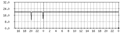
Figure 2 shows the number of the required labels and cut-through ratios for the outgoing traffic from the AS. In figure 2, the cut-through ratio is almost the same when the disconnect timer interval is more than 60 seconds. This result indicates that the value of the disconnect timer interval should be 60 seconds. The number of labels with the host-pair packet stream outgoing from the AS is 1131, when the disconnect timer interval is 60 seconds.
The result shows that a large number of labels are required for the conventional traffic-driven mapping with the host-pair packet stream in the Internet backbone area.
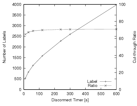
Figure 2: Number of labels and cut-through ratio for inter AS
In this subsection, we describe the number of required labels and the cut-through ratio for the flow aggregated traffic-driven mapping, that is used the ingress-egress packet stream. Here, the label is mapped with the set of packets which have the same destination network prefix. The parameters applied in the LSR are the same as the conventional traffic-driven mapping. Figure 3, 4 show the number of the required labels and the cut-through ratio. As same as the previous evaluation, the disconnect timer value is selected as 60 seconds. At the AS border router, the number of labels are 542. The cut-through ratio is 80 %. The number of labels with this policy are 48% of that with the traffic-driven mapping with the host-pair granularity, and 1.1% of that with the topology-driven mapping with the destination granularity.
The cut-through ratio of the flow aggregated traffic-driven mapping is better than that of the traffic-driven with the host-pair. And, the cut-through ratio for the topology driven mapping is further better than that of the flow aggregated traffic-driven mapping. However, the cut-through ratio with the flow aggregated traffic-driven mapping should be enough large for the actual operation, i.e., it is more than 80%.
Based on the above evaluations, we conclude that the aggregated traffic-driven mapping is better than the topology-driven mapping because the proposed label mapping policy needs fairly small number of labels, while achieving high cut-through ratio. In other words, the above result shows tha the flow aggregated traffic-driven mapping policy is better when LSPs are established between ASes.
| Label Mapping Policies | # of Labels | Cut-through Ratio [%] |
|---|---|---|
| Topology/Destination | 48385 | 100 |
| Traffic/Host-pair | 1131 | 68 |
| Traffic/Destination | 542 | 86 |
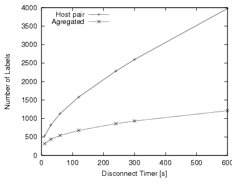
Figure 3: Number of labels for inter AS
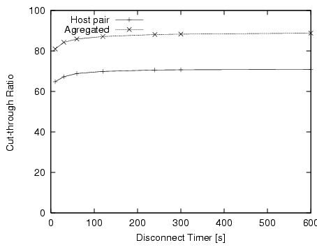
Figure 4: Cut-through ratio for inter AS
This section proposes and evaluates the Hybrid Label Mapping Policy.
For the inter AS environment, the aggregated traffic-driven label mapping is proposed. The aggregated traffic-driven label mapping policy reduces the number of LSPs and increases the cut-through ratio. The result shows on demand LSP setup procedure is useful at the AS border router which has the full-route routing table, because small number of the routing entries are referred when the packets are forwarded.
For the intra AS environment, we need to be establish an LSP from a router in an AS to a router outside of the AS because the intermediate LSRs want to cut-through the network layer procedure. A label mapping policy for the intra AS is also proposed and evaluated below.
The aggregated traffic-driven label mapping may not be always efficient in the intra AS, due to the following reasons.
The followings would be possible procedures to establish an LSP for intra AS.
The above policies are evaluated from the viewpoint of the trade off between evaluated the required number of LSPs and the control overhead (i.e., LSP setup overhead).
Policy 4 is better than policy 3. This is because the number of LSPs with policy 4 are smaller than that with policy 3, when MPLS domain is a subset of AS. With the policy 3, LSR establishes multiple LSPs to the same egress router, because the egress router is on the path of multiple routing entries.
As we evaluated in [11], the number of labels with the policy 4 is about two times less than that with policy 1.
The policy 4 reduces LSP setup procedure overhead, since it establishes LSPs in advance. Furthermore, the number of LSPs with policy 4 should not large, because the number of the ingress routers should not large in one AS. As a result, we conclude that the policy 4 is better than the policy 2, even if the number of LSPs with the policy 2 is smaller than that with the policy 4.
Based on the above evaluations and discussions, we propose the following label mapping policy in the LSR system, i.e., Hybrid Label Mapping Policy. For intra AS, the topology-driven mapping based on ingress-egress routers is applied to. For inter AS, the aggregated traffic-driven mapping is applied to.
Figure 5 shows an operational overview of the proposed label mapping policy. The network contains multiple ASes, and ASes are internetworked by the boarder routers. Within the AS, the topology-driven based semi-permanent (i.e., long-life) LSP are established among the border routers. For the packet stream to the outside own AS, the corresponding label is dynamically allocated at the AS border router while the packets are forwarded to the destination network. Once the activity of packet forwarding decreases, the corresponding LSP is released. Also, when we define the packet flow as the set of packets which have the same destination network prefix, the packet flows can be aggregated at the AS border router. This flow aggregation can also reduce the required number of labels in the LSR system.
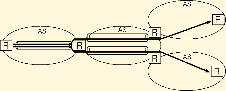
Figure 5: Hybrid Label Mapping
In order to achieve the "Hybrid Label Mapping", we proposed to use the label stack encoding [9] mechanism. Figure 6 shows an example of LSPs through multiple AS. Top label, e.g., VPI/VCI in ATM, is used for LSP in an AS. The label distribution is performed between the neighbor LSRs. In figure 6, the LSP from R1 to R3 uses the top label. The label distribution protocol is performed between R1 and R2, R2 and R3.
Second level of label, e.g., shim header, is used among AS. This label is distributed between AS border router. For example, in figure 6, the label distribution of the second label is performed between R1 and R3. When R1 sends the packet to R5, R1 puts the second and the top labels before the IP datagram header. In this example, the top label uses for the LSP toward R3, and the second label is used for the LSP toward R8 or R7. R2 forwards the packet using the top label for the cut-through forwarding. R3 forwards the packet using the second label because R3 is the LSP termination node regarding the top label. R3 puts the top label toward R5 and the second label toward R8.
Using the above algorithm, the required number of top level label will be small enough to implement. This is because the LSPs are established only among AS border routers using OSPF flow aggregation, described in the following subsections. Second label is established by the traffic-driven label mapping for the destination network.
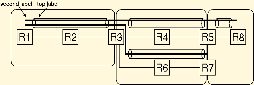
Figure 6: Example of LSPs using Label Stack
An OSPF router, which uses an OSPF routing protocol, has the complete network topology and link cost information in the belonging OSPF domain. Also, every OSPF area border router informs the external network reachability information to the neighbor OSPF router(s). All OSPF routers obtains exactly the same topology, link cost and external network reachability information through the OSPF message exchange between the neighbor OSPF router(s). Every OSPF router calculates an appropriate next hop router using these informations with the same shortest path algorithm.
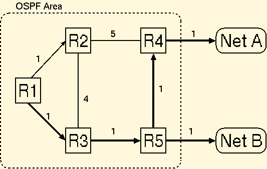
Fig. 7 shows an example of OSPF route calculation. This figure shows a topology information and a cost of links at R1. The packet transmission path from R1 to the destination is described as the bold line. When R1 wants to send a packet to R2, R1 sends the packet to R2. When R1 wants to send a packet to R3 or R4 or R5, R1 sends the packet to R3. When R1 wants to send a packet to network A, R1 sends the packet to R3. This is because R1 knows the network A is reachable through border router R4, and the routing path through R4 is the shortest path to network A. Finally, when R1 wants to send a packet to network B, R1 sends the packet to R3. This is because the network B is reachable through border router R5, and the routing path through R5 is the shortest path to network B.
In this subsection, we describe how to reduce the number of labels using OSPF information. An LSP is established between an ingress and egress routers which are border routers in the OSPF area. In this procedure, packets which are forwarded from the ingress router to the egress router are transmitted through the LSP, that is established among the boarder routers. The following three information has to be obtained by each boarder router.
There are two methods to achieve the first function. One is automatic configuration, the other is manual configuration. In this paper, the manual configuration is applied to. Regarding the second function, LSR establishes the LSP using a label distribution protocol. The evaluated system below uses the FANP(Flow Attribute Notification Protocol) as the label distribution protocol. With the third function, all packets forwarded through the same boarder router use the LSP between the corresponding ingress and egress routers. In other words, even when the destination network is different, the packets use the same LSP, when the OSPF indicates these packets should be forwarded through the same border router. As a result, all packets forwarded through the same border router can share a single LSP between the corresponding ingress and egress routers.
Since the packet flows forwarded through the same egress router are aggregated into the shared single LSP, this label switch packet forwarding policy is denoted as the "flow aggregation using OSPF information", in this paper.
Figure 8 shows an example of an LSP setup from the ingress router R1. A network manager configures that R4 and R5 are egress routers. R1 establishes the LSP to each egress routers. An LSP to the egress router R4 is R1 R3 R5 R4. In the figure 7, the destinations through R4 are R4 itself and the network A. Therefore, the packets to R4 and the network A are transferred through the same LSP from R1 to R4. In other words, the packets to R4 and to the network A from R1 share the single LSP. An LSP to R5 establishes through R1 R3 R5. This LSP forwards the packets to R5 and the network B. In this example, two ingress-egress LSPs are established using the OSPF information.
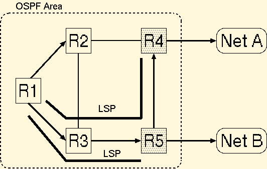
Figure 8: Example of LSP setup
We implement the LSR system, which uses ingress-egress granularity using a CSR system, which is one of an implementation of LSR. We evaluate this implementation at an LAN environment. The network has 5 edge routers and 1 core router, with a star topology. Figure 9 shows the number of LSPs at the core router. X-axis shows the time. Y-axis shows the number of established LSPs. The number of LSPs are 20 for the most of the time. This number (20) is the ideal number with this system configuration. The ideal number should be , where N are the number of the edge routers. The number of LSPs are sometimes less than 20. When the number of LSPs decrease, the edge router(s) was(were) rebooted and the number of border routers in the OSPF database decreased.
The result shows that the implemented OSPF flow aggregation policy works correctly, in the LAN environment.
In this paper, we discuss the label mapping policy in an inter AS and intra AS. And, we propose the hybrid label mapping policy. It is mixture of the topology-driven mapping with the ingress-egress granularity in an intra AS and the traffic-driven mapping with the destination granularity. Also, we discuss and implement the flow aggregation using OSPF information, which is one procedure of the topology-driven mapping with the ingress-egress granularity. The implementation works correctly in the LAN environment. One of the further study item would be the comparison of the number of labels for the topology-driven mapping with the ingress-egress granularity and the aggregated traffic-driven mapping in an intra AS environment.